
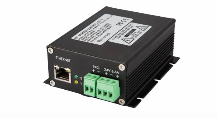
Beleuchtungscontroller / Blitzsteuerung
HPSC1
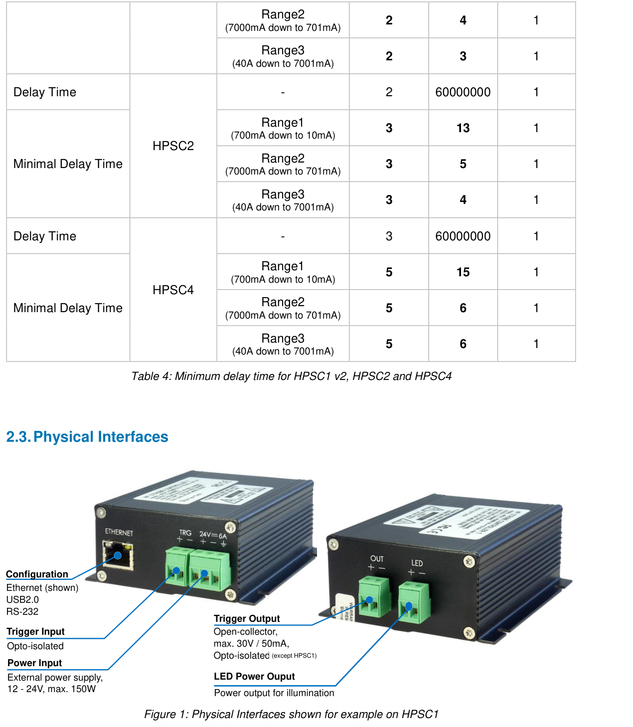
- Schnittstelle: Ethernet
- Ausgangskanäle: 1
- Blitzstrom: max. 40 A @ 48 V
- Dauerstrom: max. 5 A @ 24 V
- Pulsweite: 1 µs bis 1000 ms
Bei 24-VDC-Ausführungen ist für den Dauerbetrieb kein Beleuchtungscontroller erforderlich. Ein Controller kann optional zur Helligkeitsregelung oder für besondere Schalt- und Blitzfunktionen eingesetzt werden. SC-Ausführungen benötigen einen geeigneten Beleuchtungscontroller oder eine Stromquelle mit Strombegrenzung.
Specifications
Technical Specifications
General technical and commercial data
Design & Mechanics
- Housing
- Black anodized aluminum case
- Weight
- HPSC1: 270 g; HPSC1 v2: 285 g
Additional Technical Specifications
- Pulse range
- 1 µs bis 1000 ms, 1 µs Auflösung
Supply & Output Power
- Flash current
- max. 40 A @ 48 V
- Continuous current
- max. 5 A @ 24 V
- Operating modes
- Continuous, External Trigger, Internal Trigger, Software Trigger, External Switch
- Max. voltage
- 48 V pulsed / continuous
- Max. current
- 40 A @ 48 V
- Ambient Temperature
- From -5 °C/+23°F up to +50 °C/+122°F
- Versorgung
- 12 V – 24 V DC (min 11 V, max 26 V) at max. 6,5A
- Compliance
- CE, FCC, RoHS2
Channels, triggers & interfaces
- Interface
- Ethernet
- Output channels
- 1
- Pulse width
- 1 µs bis 1000 ms
- Current resolution
- up to 1 mA
Electrical characteristics
Model-dependent characteristics
In narrow view, the table can be shifted sideways.
| variant | Electrical characteristics | Measured values and classification | |||
|---|---|---|---|---|---|
| variant | Channels | Supply Voltage | Output voltage | Continuous current (output) | Power consumption |
| HPSC1 | 1 | 12 V – 24 V DC (min 11 V, max 26 V) at max. 6,5A | 48 V (pulsed/continuous) | 4A @ 24 V (without heat sink, max. 25 °C ambient) 5A @ 24 V (with heat sink) | Max. 150 W (depending on load) |
| HPSC1 v2 | 1 | 12 V – 24 V DC (min 11 V, max 26 V) at max. 6,5A | 48 V (pulsed/continuous) | 4A @ 24 V (per channel) up to 5A @ 24 V (in total) | Max. 150 W (depending on load) |
No version matches these filters.
Notes on the specifications table
HPSC1
Operating modes: Continuous operation, external trigger, internal trigger, software trigger, external switching operation
Maximum output voltage: 48 V (strobe and continuous operation)
Maximum pulse current: 40 A at 48 V (per channel)
Current resolution: up to 1 mA
Maximum continuous current: 4 A at 24 V (without heat sink, max. 25 °C ambient temperature) 5 A at 24 V (with heat sink)
Pulse duration: 1 µs – 1000 ms, resolution 1 µs
Maximum frequency with external trigger: 4,9 kHz
Maximum frequency with internal trigger / external switching operation: 997 Hz
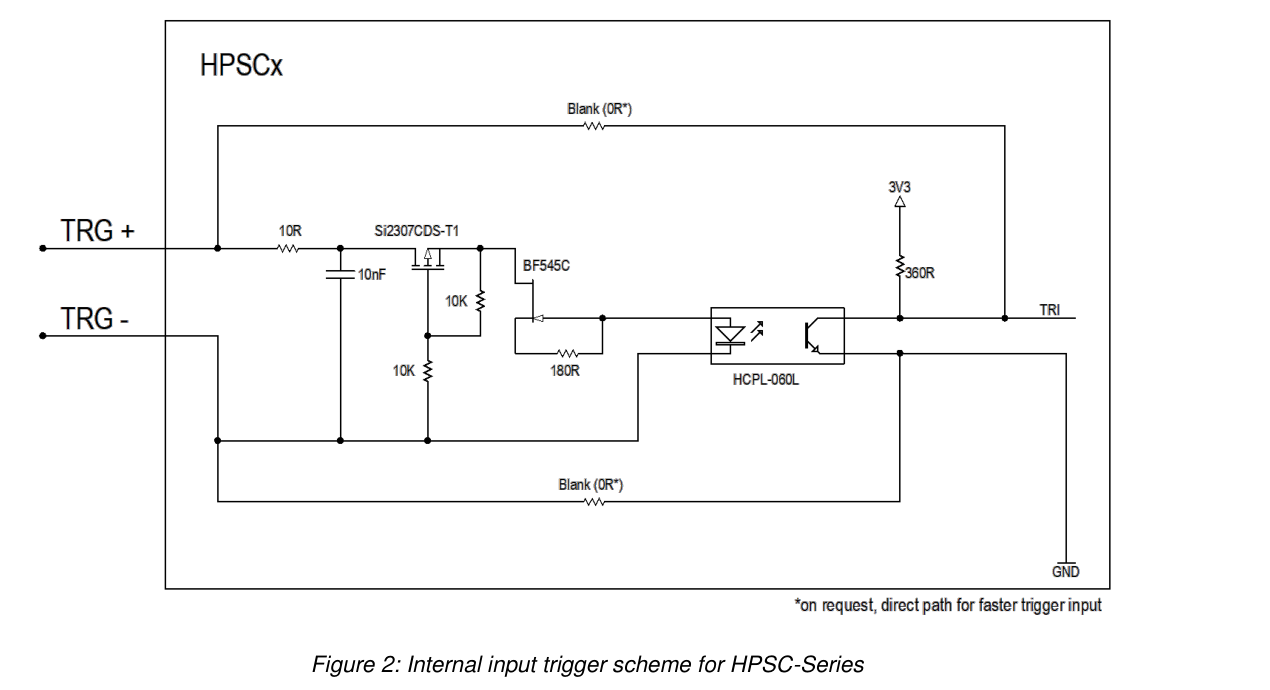
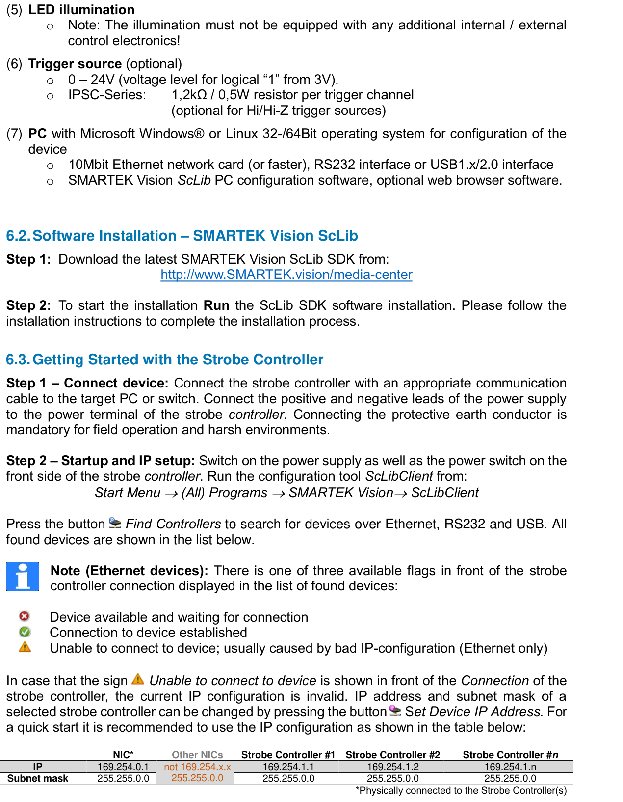
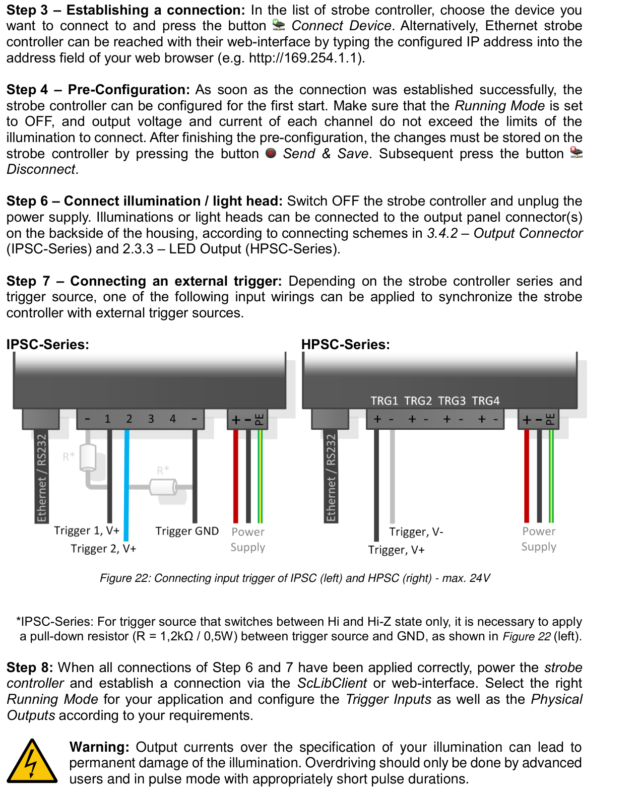
Trigger input: Optically isolated, high level at 3 V – 24 V; positive or negative edge
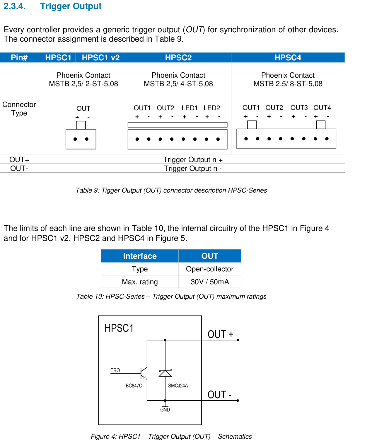
Trigger output: Open-collector, max. 30 V / 50 mA
Interfaces: Ethernet (10Base-T), RS-232 or USB1.x/2.0
Supply: 12 V – 24 V DC (min. 11 V, max. 26 V) at max. 6,5 A
Power consumption: Max. 150 W (load-dependent)
Dimensions (H × W × L): 39 x 88 x 103 mm
HPSC1 v2
Maximum continuous current: 4 A at 24 V (per channel) up to 5 A at 24 V (total)
Pulse duration: 1 µs – 60 s, resolution 1 µs
Maximum frequency with external trigger: 50 kHz
Maximum frequency with internal trigger / external switching operation: 25 kHz
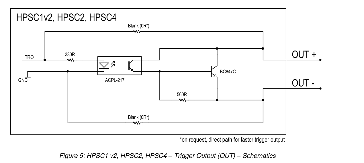
Trigger output: Optically isolated, max. 30 V / 50 mA
Interfaces: Ethernet (10Base-T/100Base-TX) RS-232 or USB1.x/2.0 on request
Connection and PIN assignment
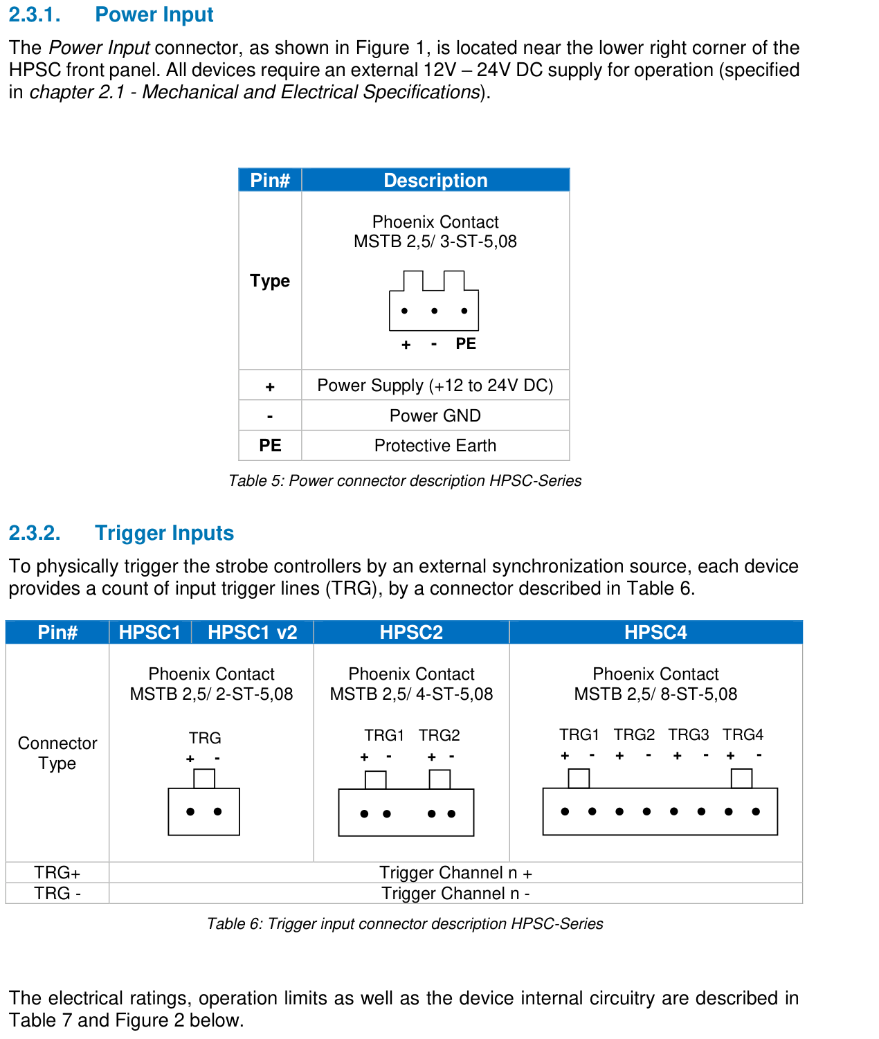
Phoenix Contact MSTB 2,5/3-ST-5,08 · Controller Supply
Controller supply · Phoenix Contact MSTB 2,5/3-ST-5,08
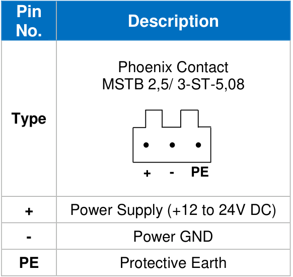
Connector layout according to original manual
| PIN | Farbe | Wire color | Function |
|---|---|---|---|
| + | – | – | Power Supply +12 to 24V DC |
| - | – | – | Power GND |
| PE | – | – | Protective Earth |
Terminal designations as per original; no additional numeric PIN numbers derived.
RJ45 · Ethernet · Configuration
Ethernet · Configuration · RJ45
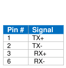
Connector layout according to original manual
| PIN | Farbe | Wire color | Function |
|---|---|---|---|
| 1 | – | – | TX+ |
| 2 | – | – | TX- |
| 3 | – | – | RX+ |
| 6 | – | – | RX- |
The original lists these four contacts for Ethernet. Other contacts are not added as unassigned.
USB-B · USB · Configuration, if available
USB · Configuration, if available · USB-B
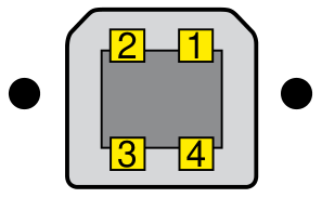
USB-B pinout according to original manual
| PIN | Farbe | Wire color | Function |
|---|---|---|---|
| 1 | – | – | V+ |
| 2 | – | – | D- |
| 3 | – | – | D+ |
| 4 | – | – | V- |
Applies exclusively to device versions with a USB interface. USB 1.x/2.0, cable type A to B; virtual serial COM port according to manual.
D-Sub 9-pin · RS232 · Configuration
RS232 · Configuration · D-Sub 9-pin
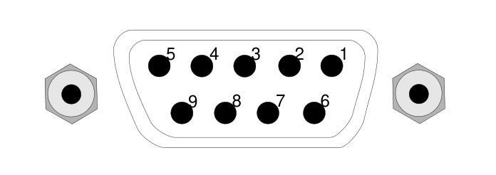
Connector layout according to original manual
| PIN | Farbe | Wire color | Function |
|---|---|---|---|
| 2 | – | – | TxD on controller → RxD on PC |
| 3 | – | – | RxD at controller ← TxD at PC |
| 5 | – | – | GND |
| 4 ↔ 6 | – | – | Handshaking loop back |
| 7 ↔ 8 | – | – | Handshaking loop back |
| 1, 9 | – | – | Not connected |
Note the controller side. In the original, the signal names of the PC side are also compared.
Phoenix Contact MSTB 2,5/2-ST-5,08 · HPSC1 · Trigger Input
1-kanalig · HPSC1 · Trigger-Eingang · Phoenix Contact MSTB 2,5/2-ST-5,08
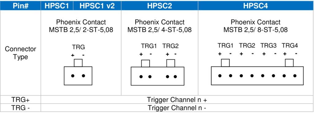
Model columns according to original manual
| PIN | Farbe | Wire color | Function |
|---|---|---|---|
| TRG1 + | – | – | Trigger Channel 1 + |
| TRG1 - | – | – | Trigger Channel 1 - |
HIGH: >3VDC; LOW: 0–1,4VDC; recommended 0–24VDC; absolute limit 30VDC. Current per input 6–10mA (manual page 12). Image shows multiple models; note appropriate column.
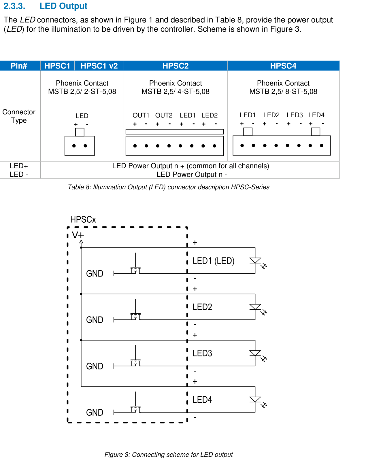
Phoenix Contact MSTB 2,5/2-ST-5,08 · HPSC1 · LED Output
1-kanalig · HPSC1 · LED-Ausgang · Phoenix Contact MSTB 2,5/2-ST-5,08
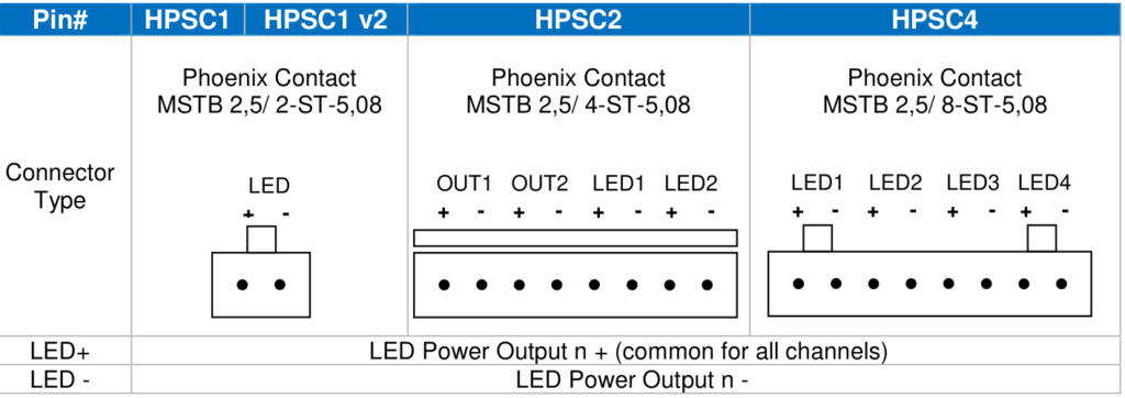
Model columns according to original manual
| PIN | Farbe | Wire color | Function |
|---|---|---|---|
| LED1 + | – | – | LED Power Output 1 + (common for all channels) |
| LED1 - | – | – | LED Power Output 1 - |
Terminal designations from the respective model column; no additional numeric assignment derived. HPSC2: Illustration shows LED and trigger output terminals together.
Phoenix Contact MSTB 2,5/2-ST-5,08 · HPSC1 · Trigger Output
1-kanalig · HPSC1 · Trigger-Ausgang · Phoenix Contact MSTB 2,5/2-ST-5,08
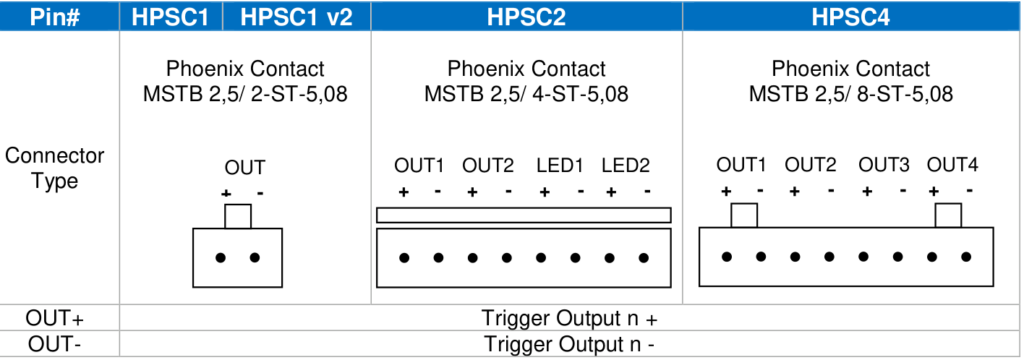
Model columns according to original manual
| PIN | Farbe | Wire color | Function |
|---|---|---|---|
| OUT1 + | – | – | Trigger Output 1 + |
| OUT1 - | – | – | Trigger Output 1 - |
Terminal designations from the respective model column; no additional numeric assignment derived. HPSC2: Illustration shows LED and trigger output terminals together. Trigger output: open collector, max. 30V / 50mA. Note different circuits for HPSC1 and HPSC1 f2/HPSC2/HPSC4 on pages 15/16.
Dimensional drawing


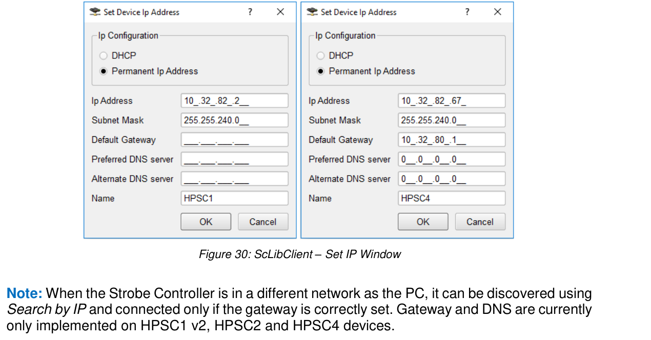
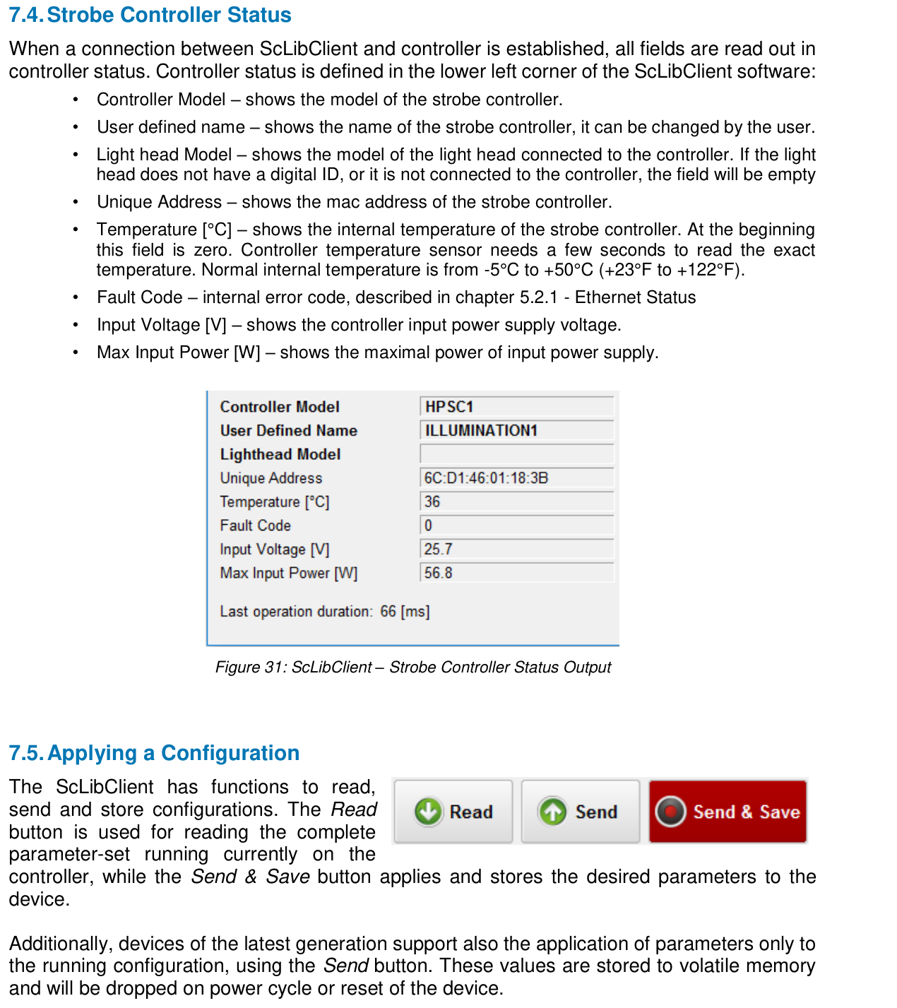
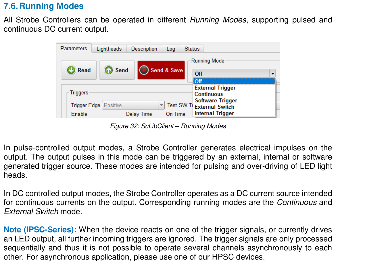
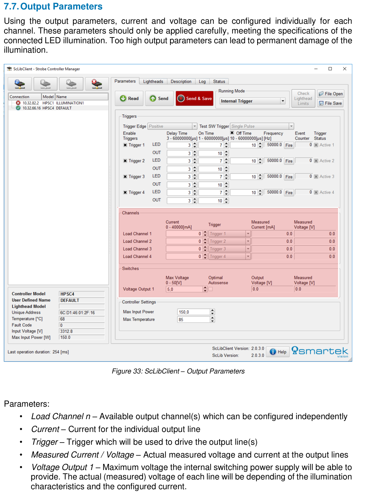
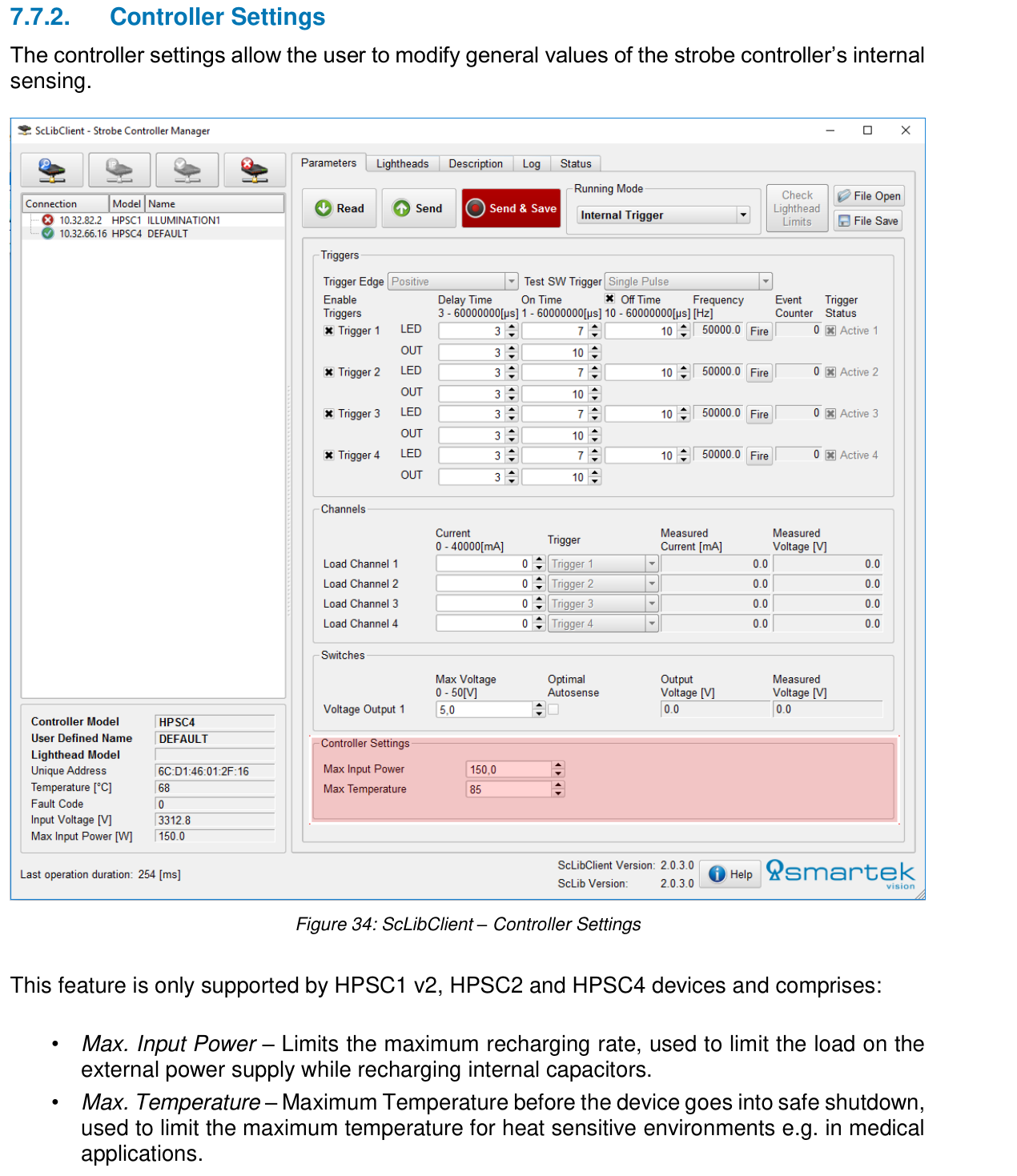
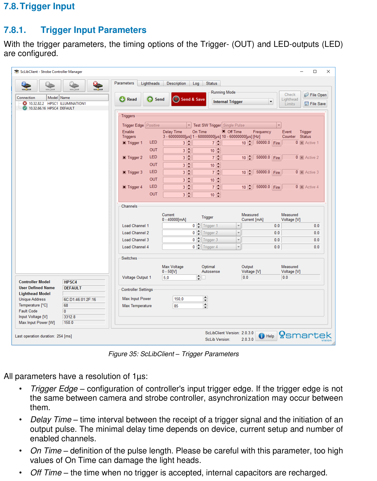
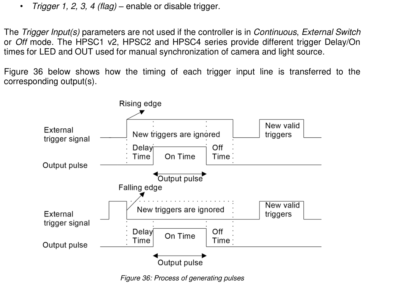
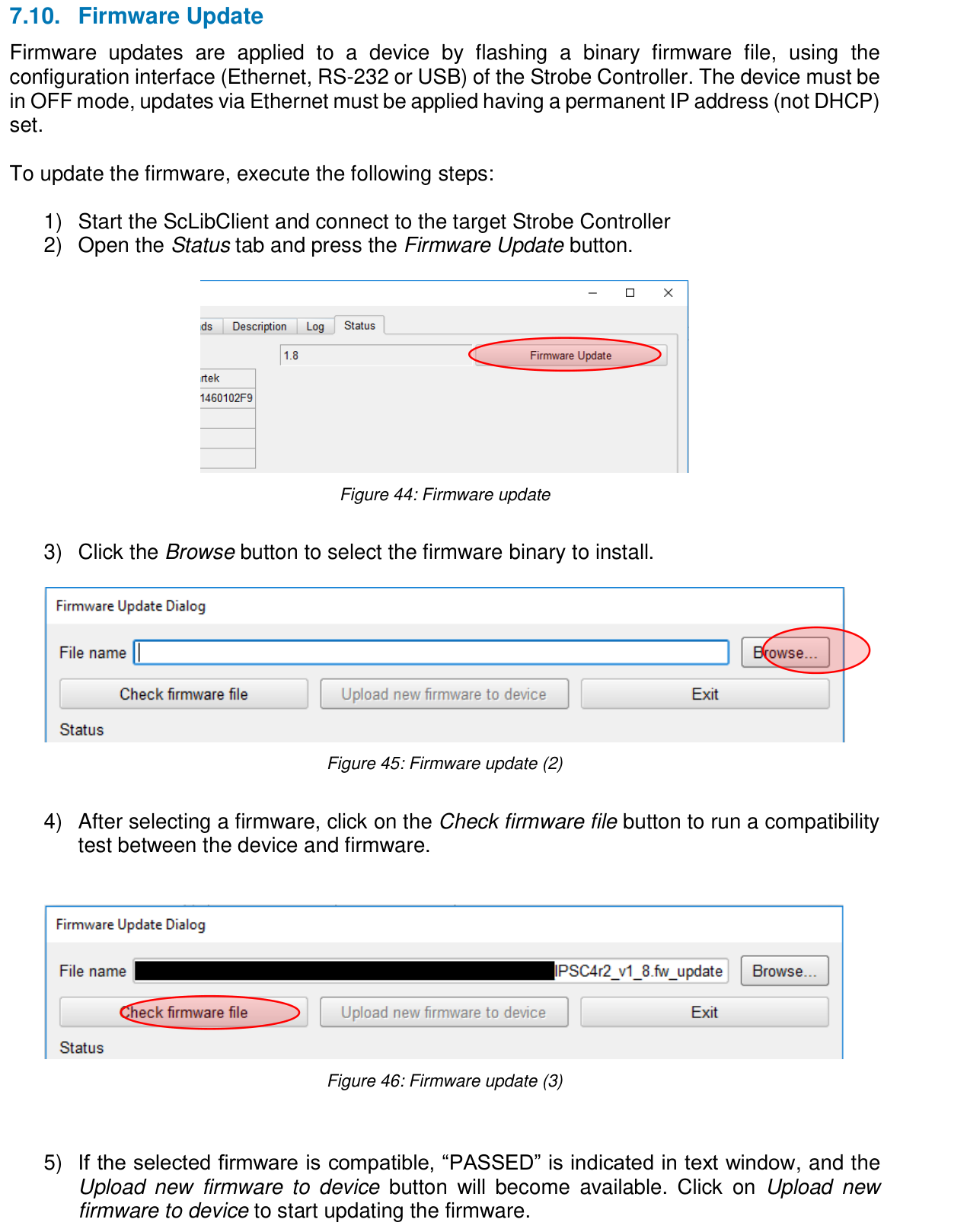
Operating instructions
Connection and control
Connection and control
Custom inquiry
Select matching controller
Please specify your lighting, the required number of channels, operating mode, and the desired control. We will check the appropriate combination and prepare your quote.
CAD data for your planning
We would be pleased to support you with CAD data and information on the mechanical integration of your desired version.
Request CAD data →Documents & CAD
Downloads
Bitte melden Sie sich mit Ihrem freigeschalteten Kundenkonto an.
Anmelden / RegistrierenIhre Kundenpreise sind freigeschaltet. Ihr hinterlegter Rabatt ist bereits berücksichtigt.
Open original price list (without customer discount) I-CON
 IPSC1
Product inquiry
HPSC1 check for your application
Briefly describe your Prüfaufgabe.

