
PWM (short for pulse-width modulation) is a digital modulation technique in which a technical quantity (e.g., electrical voltage) alternates between two values. In this process, a square wave pulse is generated (modulated) at a constant frequency, with varying pulse width or duration. The ratio between the pulse duration and the period duration (sum of pulse duration and pause duration) is referred to as the duty cycle.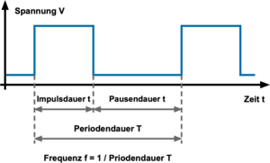 (Source: www.elektronik-kompendium.de)
A PWM signal must be generated by a PWM generator. For this purpose, a frequency is set (the reciprocal of the period duration) and the duty cycle is specified, which corresponds to the duration of the pulse within the period.
Pulse-width modulation, or PWM for short, is also referred to as pulse-duration modulation (PDM), pulse-length modulation, or subharmonic modulation.
English: pulse width modulation (PWM), pulse time modulation (PTM), or pulse duration modulation (PDM).
A PWM signal is suitable …
– as a control signal in open- and closed-loop control systems.
– as a measurement signal.
– for data transmission.
– for driving a load with variable voltage using the average voltage value, which can be adjusted by varying the pulse width.
PWM signal as a control signal
There are applications in open- and closed-loop control where a separate PWM signal is used to transmit control information. The information is contained within the duty cycle of the PWM signal.
Examples include:
– Servomotor position control: PWM signals can be used to set the position (angle) of a servomotor.
– Fan speed control: A PWM signal can be used to regulate the speed of cooling fans.
– AC drive power control: PWM signals can be used to control the output of AC drives, such as inverters or variable frequency drives.
PWM signal as a measurement signal
A PWM signal generator can be used to generate any square wave signal. Within measurement applications, one can, for example, measure the time required to receive a specific number of pulses from a given PWM signal.

