
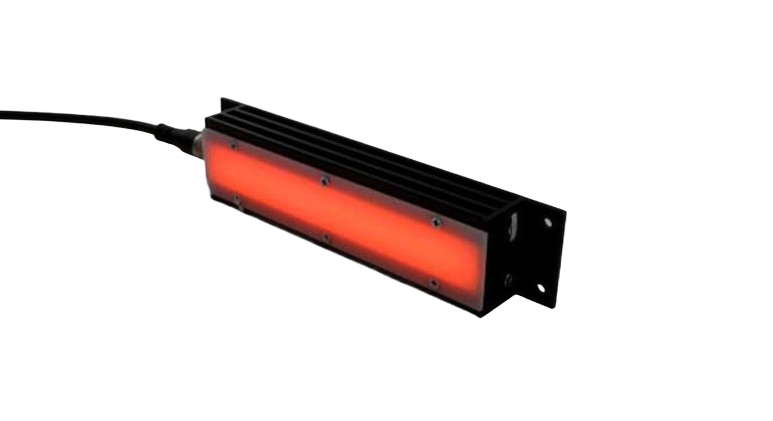
Hintergrundbeleuchtungen
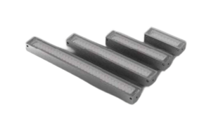
HI-LINE-2TE
- Gehäusemaß: ca. 148x22x32 mm³
- Aktive Fläche: ca. 110x15 mm²
- linienförmiges Durchlicht
Variants:
Specifications
Technical Specifications
General technical and commercial data
Design & Mechanics
- Housing dimensions
- approx. 148x22x32 mm³
- Aktive Fläche
- approx. 110x15 mm²
- Housing
- Aluminum blasted natural anodized
- Front / Cover
- PMMA
- Weight
- approx. 115 g
- LEDs
- 16
Operation & Connection
- Electrical versions and connections
- 24 VDC · 1-channelM8 Connector 4-pin
- 24 VDC with switching input · 1-channelM8 Connector 4-pin
- SC · 1-channelM8 Connector 4-pin
- Ambient Temperature
- max. 50 °C recommended
- Protection class (IP)
- IP50
- electrical protection class
- III, safety extra-low voltage operation
- Compliance
- CE, RoHS
- service life
- The service life of LEDs is in the range of several 10.000 to 100.000 hours and is generally very high, but depends on many different factors such as ambient temperature, current load, etc.
Service life explained in WikiLED →
Model-dependent characteristics
Model-dependent characteristics
In narrow view, the table can be shifted sideways.
No version matches these filters.
Notes on the specifications table
Additional light colors and versions from UV to infrared available upon request.
Connection and PIN assignment
M8 Connector 4-pin · 24VDC · 1-channel
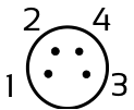
Front view of housing
| PIN | Farbe | Wire color | Function |
|---|---|---|---|
| 1 | brown | brown | + 24V |
| 3 | blue | blue | - (Kanal 1 / Channel 1) |
Exclusively einkanalig Ausführung: PIN 1 is +24V, PIN 3 is minus (channel 1). The connection to PIN 4 shown in parentheses in the original is not part of this Anschlussbelegung. Its German and English channel numbers contradict each other; technical clarification is still required for mehrkanalig use.
M8 Connector 4-pin · SC · 1-channel
Front view of housing
| PIN | Farbe | Wire color | Function |
|---|---|---|---|
| 4 | black | black | + |
| 3 | blue | blue | - (Kanal 1 / Channel 1) |
Single-channel version: PIN 4 is positive, PIN 3 is negative (channel 1). The optional second channel at PIN 2 shown in brackets in the original does not belong to this single-channel assignment. The separate two-channel profile applies to the two-channel version.
Dimensional drawing

Operating instructions
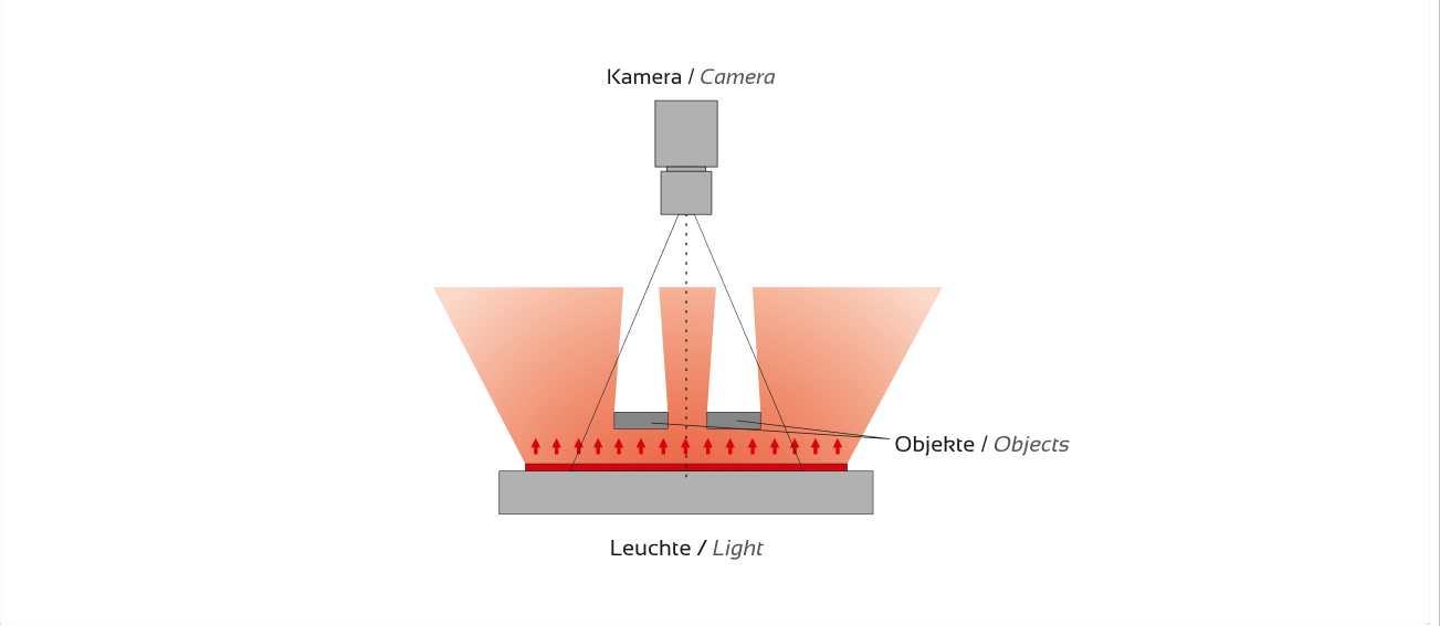
Application, light guidance, and optics
Application and light guidance
Price & order code
HI-LINE-2TE Configure
Select the desired version. The available options and item combinations are derived directly from the respective product price list.
Loading product data…
Bitte melden Sie sich mit Ihrem freigeschalteten Kundenkonto an.
Anmelden / RegistrierenIhre Kundenpreise sind freigeschaltet. Ihr hinterlegter Rabatt ist bereits berücksichtigt.
| Part number | Ihr Kundenpreis | Description |
|---|
Prices according to the linked price list. The approved price list version is authoritative.
Accessories
Select accessories suitable for the power supply, connection, and testing task.
Kabel & Steckverbindungen
Kabelsatz auswählen und konfigurieren →
| Part number | Description / Version | Enquiry basket |
|---|---|---|
| S12-M85M | 5m Kabel M8-Kupplung gerade 4-polig auf offene Aderenden | |
| S12-M810M | 10m Kabel M8-Kupplung gerade 4-polig auf offene Aderenden |
Fronten & Diffusoren
Frontmaterialien, Lichtverteilung und Transmissionswerte im WikiLED →
| Part number | Description / Version | Enquiry basket |
|---|---|---|
| S230-13A | Front HI-LINE-2TE klar antireflex | |
| S230-43S0 | Diffusor HI-LINE-2TE Material 060 (Trans. 45%) |
Controller & Ansteuerung
Bei 24-VDC-Ausführungen ist für den Dauerbetrieb kein Beleuchtungscontroller erforderlich. Ein Controller kann optional zur Helligkeitsregelung oder für besondere Schalt- und Blitzfunktionen eingesetzt werden. SC-Ausführungen benötigen einen geeigneten Beleuchtungscontroller oder eine Stromquelle mit Strombegrenzung.
| Part number | Description / Version | Enquiry basket |
|---|---|---|
| S510-0102 | Beleuchtungscontroller IPSC1 | |
| S510-0202-E-V2 | Beleuchtungscontroller HPSC1 | |
| S520-0102 | Beleuchtungscontroller IPSC2 | |
| S540-0102 | Beleuchtungscontroller IPSC4 | |
| S540-0200-E | Beleuchtungscontroller HPSC4 |
Documents & CAD
Downloads
Bitte melden Sie sich mit Ihrem freigeschalteten Kundenkonto an.
Anmelden / RegistrierenIhre Kundenpreise sind freigeschaltet. Ihr hinterlegter Rabatt ist bereits berücksichtigt.
Open original price list (without customer discount) HI-LINE-4TE
 HI-LINE-D3
Product inquiry
HI-LINE-2TE check for your application
Briefly describe your Prüfaufgabe.

