
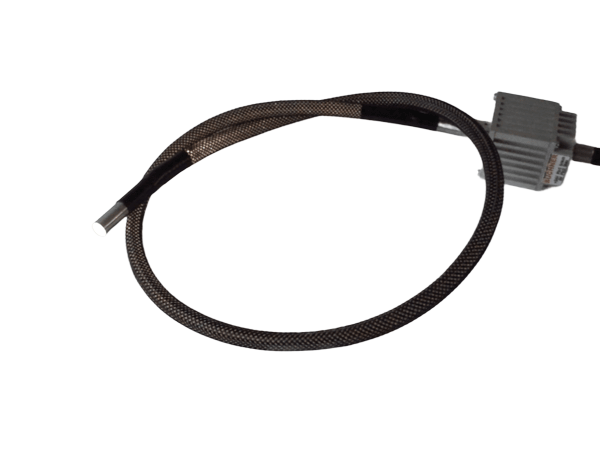
Lichtleitersysteme
LIGHTPIN-Guide
- Gehäusemaß: ca. 33 x 49 x 33 mm³
- Lichtaustritt: ca. 8 mm
- High-Power LED-System
Specifications
Technical Specifications
01
General technical and commercial data
Design & Mechanics
- Housing dimensions
- approx. 33 x 49 x 33 mm³
- Housing
- Aluminum black anodized
- Weight
- approx. 75 g without fiber optic
- LEDs
- 1 High-Power-LED
Additional Technical Specifications
- Light emission
- approx. 8 mm
Operation & Connection
- Ambient Temperature
- max. 50 °C recommended
- Protection class (IP)
- Ip65
- Connection
- M8 connector (4-pin)
- Versorgung
- 7 - 35 VDC SC-Typ: For use with a controller
- service life
- The service life of LEDs is very high, but depends on many different factors such as ambient temperature, current load, etc.
Service life explained in WikiLED →
02
Model-dependent characteristics
Model-dependent characteristics
In narrow view, the table can be shifted sideways.
No version matches these filters.
Notes on the specifications table
The intensity specifications are approximate values in continuous operation (DC).
Measuring distance: 200 mm below the bottom edge of the housing.
Additional light colors and versions from UV to infrared available upon request.
03
Connection and PIN assignment
M8 Connector 4-pin · 24VDC · 1-channel
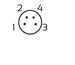
| PIN | Farbe | Wire color | Function |
|---|---|---|---|
| 1 | brown | brown | + 24V |
| 3 | blue | blue | - |
M8 Connector 4-pin · SC · 1-channel
| PIN | Farbe | Wire color | Function |
|---|---|---|---|
| 4 | black | black | + |
| 3 | blue | blue | - |
M8 Connector 4-pin · 24VDC with switching input · 1-channel
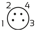
Front view of housing
| PIN | Farbe | Wire color | Function |
|---|---|---|---|
| 1 | brown | brown | + 24V |
| 3 | blue | blue | - |
| 4 | black | black | Switching input* |
* ON: 3,7V - 24V / OFF: < 3,0V
04
Dimensional drawing

05
Operating instructions
06
Application, light guidance, and optics

Custom inquiry
Configure desired version
Let us know your requirements. We will personally confirm the right version, part number, and price.
CAD data for your planning
We would be pleased to support you with CAD data and information on the mechanical integration of your desired version.
Request CAD data →Documents & CAD
Downloads
 LIGHTPIN-Guide
Product inquiry
LIGHTPIN-Guide check for your application
Briefly describe your Prüfaufgabe.
Product: LIGHTPIN-Guide

