
If a component moves during image acquisition, contours and features in the image can become blurred. Shorter effective exposure times limit this motion blur but require sufficient light. Camera, lighting, and control are therefore coordinated to match speed, field of view, and inspection features.
Typical inspection tasks
- Capturing components on conveyor belts and in indexed systems.
- Acquiring codes and markings during movement.
- Supporting fast sorting, assembly, and presence checks.
- Targeted imaging of short process phases or rotating components.
Which light is right for the task?
Deriving exposure time from movement and inspection features
The distance traveled during acquisition is determined by speed and exposure duration. The amount of permissible blur depends on the object resolution and the smallest feature to be evaluated. Only then can the required time range be meaningfully derived.
Concentrating light spatially on the inspection area
Ring, line, or area lighting matching the geometry brings light into the relevant image area. Distance and beam angle must match the field of view; a larger amount of light alone does not resolve unfavorable reflections or unsuitable illumination.
Synchronizing flash and camera appropriately
A short light pulse can limit the effective acquisition time if the camera, shutter type, and trigger sequence are compatible. Pulse duration, delay, repetition rate, and ambient light are considered together. Compatibility of the acquisition sequence must be checked, especially with rolling shutter cameras.
Observing operating variants and current limits
SC versions require a suitable lighting controller or a power source with current limiting. For flash operation, the permissible current, pulse duration, and repetition conditions of the specific lighting must be observed. 24 VDC with switching input is not intended for flash operation with excessive currents. The technical specifications and the product label of the selected version are authoritative.
Example setup: Component inspection on a conveyor belt
First, the permissible motion blur is determined for the desired object resolution. From this, the exposure or light pulse duration is derived. Subsequently, lighting matching the field of view is selected, and synchronization with the camera and component detection is tested. Finally, image contrast and heat generation are checked at the actual intended cycle sequence.
Suitable products as a starting point
The following products demonstrate suitable lighting principles. Size, light color, power supply, and available options are selected for your specific inspection task.
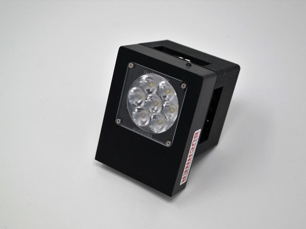
HIGHSPEED-ONE
Product from the high-speed portfolio; the appropriate version and operating conditions are coordinated with the specific acquisition sequence.
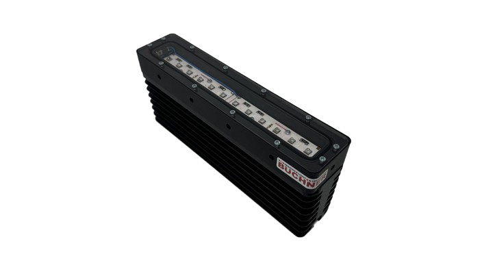
POWER-LINE-160
Line or bar lighting for suitable directional incident light setups.
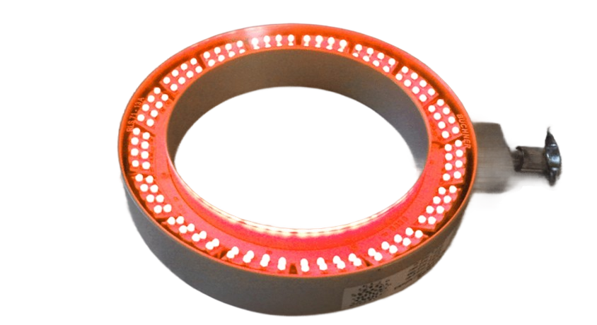
CORONA-180
Ring lighting for suitable camera-proximal incident light setups; select power supply, light color, and version based on the application.
Controllers are selected according to the chosen lighting and the required current, voltage, and time ranges.
This information helps with the selection
- Maximum component speed and direction of movement.
- Field of view, smallest inspection feature, and permissible blur.
- Camera model, shutter type, trigger, and required acquisition rate.
- Operating variant, pulse duration, repetition rate, installation space, and heat dissipation.
If possible, please send us camera and trigger data as well as information on speed and cycle sequence. This allows us to check whether continuous light is sufficient or which switched or pulsed control is suitable for the task.

