
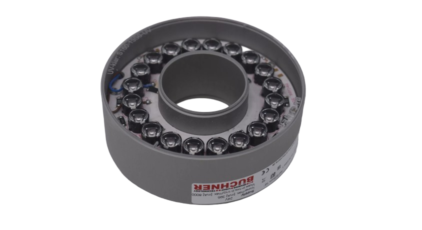
Ringbeleuchtungen
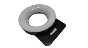
HELIOS-95
- Außen-/Innendurchmesser: ca. 96 / 39 mm
- Montage: M40,5x0,5
- Schutzart (IP): IP54
- 20 High-Power LEDs
Variants:
Specifications
Technical Specifications
General technical and commercial data
Design & Mechanics
- Outer/inner diameter
- approx. 96 / 39 mm
- Mounting
- M40,5x0,5
- Housing
- Aluminum, silver anodized
- Diffuser
- PMMA
- Weight
- approx. 235 g
- LEDs
- 20
Additional Technical Specifications
- Filter thread
- M40,5x0,5
Operation & Connection
- Electrical versions and connections
- 24 VDC · 1-channelM8 Connector 4-pin
- SC · 1-channelM8 Connector 4-pin
- 24 VDC · 4-kanalig · Polarität +M8 Connector 6-pin
- 24 VDC · 4-kanalig · Polarität -M8 Connector 6-pin
- SC · 4-channel · Polarity +M8 Connector 6-pin
- SC · 4-channel · Polarity -M8 Connector 6-pin
- Protection class (IP)
- IP54
- Ambient Temperature
- max. 50 °C recommended
- electrical protection class
- III, safety extra-low voltage operation
- Compliance
- CE, RoHS
- service life
- The service life of LEDs is in the range of several 10.000 to 100.000 hours and is generally very high, but depends on many different factors such as ambient temperature, current load, etc.
Service life explained in WikiLED →
Model-dependent characteristics
Model-dependent characteristics
In narrow view, the table can be shifted sideways.
No version matches these filters.
Notes on the specifications table
Additional light colors and versions from UV to infrared available upon request.
Connection and PIN assignment
M8 Connector 4-pin · 24VDC · 1-channel
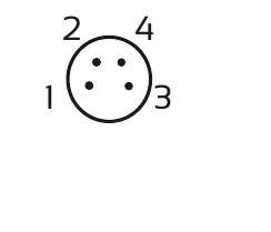
| PIN | Farbe | Wire color | Function |
|---|---|---|---|
| 1 | brown | brown | + 24V |
| 3 | blue | blue | - |
M8 Connector 4-pin · SC · 1-channel
| PIN | Farbe | Wire color | Function |
|---|---|---|---|
| 4 | black | black | + |
| 3 | blue | blue | - |
Dimensional drawing

Operating instructions
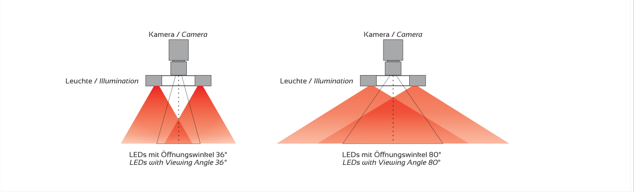
Application, light guidance, and optics
Application and light guidance

Price & order code
HELIOS-95 Configure
Select the desired version. The available options and item combinations are derived directly from the respective product price list.
Loading product data…
Bitte melden Sie sich mit Ihrem freigeschalteten Kundenkonto an.
Anmelden / RegistrierenIhre Kundenpreise sind freigeschaltet. Ihr hinterlegter Rabatt ist bereits berücksichtigt.
| Part number | Ihr Kundenpreis | Description |
|---|
Prices according to the linked price list. The approved price list version is authoritative.
Lens mounting
Lens mounting rings
Find suitable adapters for HELIOS-95 – using as few rings as possible.
A lens mount is mentioned in the product features. The thread specification has not yet been clearly confirmed. Please contact us for the appropriate mounting connection.
Design guide
Light spot calculator for ring lights
Calculates the theoretical light spot of a folded LED circuit board. The innermost LED row forms the pivot point; the circuit board slopes outward toward the workpiece. All LEDs emit light perpendicular to the circuit board plane.
Calculation details
LED rows
| Row | Radius | Recess | Working distance | Cone contact | Intersection of axes |
|---|
Model assumption: The inner LED row is the fixed pivot point. The circuit board slopes outwards towards the workpiece with β. The LEDs are perpendicular to the circuit board; the opening angle α is symmetrical around the respective optical axis. Real lenses, diffusers, and intensity limits can change the practically usable light spot.
Accessories
Select accessories suitable for the power supply, connection, and testing task.
Kabel & Steckverbindungen
Kabelsatz auswählen und konfigurieren →
| Part number | Description / Version | Enquiry basket |
|---|---|---|
| S12-M85M | 5m Kabel M8-Kupplung gerade 4-polig auf offene Aderenden | |
| S12-M810M | 10m Kabel M8-Kupplung gerade 4-polig auf offene Aderenden | |
| S12-M85M6P | 5m Kabel M8-Kupplung gerade 6-polig auf offene Aderenden | |
| S12-M810M6P | 10m Kabel M8-Kupplung gerade 6-polig auf offene Aderenden |
Montage & Objektivbefestigung
| Part number | Description / Version | Enquiry basket |
|---|---|---|
| S173-3 | CONNECT Montageadapter Baumer Verisens | |
| S173-4 | CONNECT Montageadapter Cognex Insight |
Fronten & Diffusoren
Frontmaterialien, Lichtverteilung und Transmissionswerte im WikiLED →
| Part number | Description / Version | Enquiry basket |
|---|---|---|
| S173-13A | Front HELIOS-95 klar antireflex | |
| S173-414S0-W30 | 3-D-Diffusor HELIOS-95 Material 060 30° | |
| S173-13S1 | Diffusor HELIOS-95 1-seitig sat. (Trans. 91%) | |
| S173-422S0-W45 | 3-D-Diffusor HELIOS-95 Material 060 45° | |
| S173-33S0 | Diffusor HELIOS-95 Material 017 (Trans. 90%) | |
| S173-436S0-W60 | 3-D-Diffusor HELIOS-95 Material 060 60° | |
| S173-23S0 | Diffusor HELIOS-95 Material 010 (Trans. 68%) | |
| S173-42S0 | Diffusor HELIOS-95 Material 060 (Trans. 45%) |
Polarisation
Frontmaterialien, Lichtverteilung und Transmissionswerte im WikiLED →
| Part number | Description / Version | Enquiry basket |
|---|---|---|
| S173-53S0 | Front Polfilter linear HELIOS-95 |
Controller & Ansteuerung
Bei 24-VDC-Ausführungen ist für den Dauerbetrieb kein Beleuchtungscontroller erforderlich. Ein Controller kann optional zur Helligkeitsregelung oder für besondere Schalt- und Blitzfunktionen eingesetzt werden. SC-Ausführungen benötigen einen geeigneten Beleuchtungscontroller oder eine Stromquelle mit Strombegrenzung.
| Part number | Description / Version | Enquiry basket |
|---|---|---|
| S510-0102 | Beleuchtungscontroller IPSC1 | |
| S510-0202-E-V2 | Beleuchtungscontroller HPSC1 | |
| S520-0102 | Beleuchtungscontroller IPSC2 | |
| S-0012 | I-Switch Alu 2.5A M8 (external power switch) | |
| S540-0102 | Beleuchtungscontroller IPSC4 | |
| S540-0200-E | Beleuchtungscontroller HPSC4 |
Documents & CAD
Downloads
Bitte melden Sie sich mit Ihrem freigeschalteten Kundenkonto an.
Anmelden / RegistrierenIhre Kundenpreise sind freigeschaltet. Ihr hinterlegter Rabatt ist bereits berücksichtigt.
Open original price list (without customer discount) CORONA-180
 IRIDA-180
Product inquiry
HELIOS-95 check for your application
Briefly describe your Prüfaufgabe.

